Advanced Power Management
Advanced options are available for customizing how your boards power themselves and their features.
Disabling Standalone Power Input Switching
Section titled “Disabling Standalone Power Input Switching”On Bottango Solar and Impulse, you can power the boards using the DC servo power input alone. By default, these control boards will dynamically select between powering their logic components from either the USB connection or the DC input.
If both inputs are available, they will default to the DC servo power input. If the DC servo power input is disconnected or drops voltage too low, but USB power input is available, they will attempt to do a fast switch without resetting the board.
You can, however, disable this functionality. Use the LOG PWR switch on the back to choose between accepting logic power from either DC or USB input, or from USB only. The switch is available on both Bottango Solar and Impulse.
Bottango Solar
Section titled “Bottango Solar”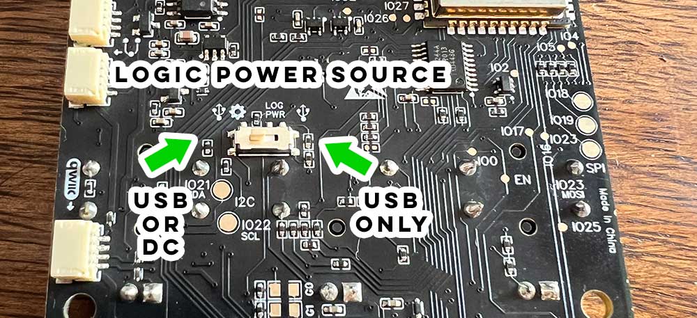
Bottango Impulse
Section titled “Bottango Impulse”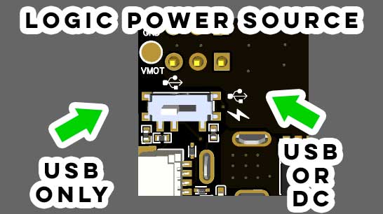
Standalone Power for Bottango Nova
Section titled “Standalone Power for Bottango Nova”When used as a show controller, Bottango Nova still needs to be powered. The easiest way is to use the USB-C port to provide a 5 V power source such as a standard phone charger, etc. You can also use the pin on the side header pins marked “VIN” to input 5 V power instead.
8.4 V Servos
Section titled “8.4 V Servos”There are high-voltage PWM servos that use 8.4 V instead of the standard 5-6 V. By making some modifications to the boards, you can use these servos if you do so with care. However, it’s important to make these changes correctly so that 8.4 V is not connected to the sensitive logic circuits or damage will occur. Higher than 8.4 V is not possible.
Bottango Impulse
Section titled “Bottango Impulse”On Bottango Impulse, selecting the USB only side of the LOG PWR switch will prevent the DC input from being used for logic power, allowing it to be used only for the servo header power pins. Check with a multimeter with 5-6 V power input first to double check that the DC input is not powering logic circuits or the 3.3 V rail.
You will need to provide an additional power source for the logic components. A standard 5 V USB phone charger and USB input will be sufficient. The “logic in” pad on the back of the board is also a place to solder in a 5-6 V logic power input.
Bottango Solar
Section titled “Bottango Solar”Because DC input is used on Bottango Solar for both servos and the onboard amp, you need to:
- Select the
USBonly side of theLOG PWRswitch to prevent the DC input from being used for logic power. - Prevent the amp circuit from being powered via the DC power input.
Bottango Solar Logic Power Input
Section titled “Bottango Solar Logic Power Input”You will need to provide an additional power source for the logic components. A standard 5 V USB phone charger and USB input will be sufficient. The “Log in” unpopulated header pin on the back of the board is also a place to solder in a 5 V logic power input.
Bottango Solar Amp Power Configuration
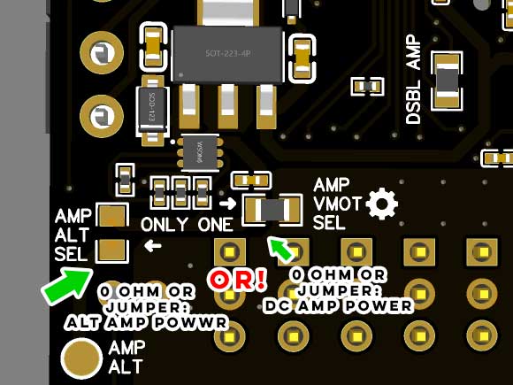
Section titled “Bottango Solar Amp Power Configuration”Desolder the 0-ohm resistor labeled “AMP VMOT SEL”, making sure that the pads are isolated from each other once the resistor is removed.
‘AMP VMOT SEL’ selects to power the onboard amp through the DC servo power input. By removing that resistor, you will prevent DC servo input from reaching the amp circuits.
After making these changes, check with a multimeter with 5-6 V input first to double check. You will need to provide an additional power source for the logic components. A standard 5 V USB phone charger and USB input will be sufficient.
However, the onboard amp will not have a power input with this setup. You can use line-out for audio, or if you need to use the onboard amp, you will need to solder a bridge on the AMP ALT SEL pads, and then solder a separate 5-6 V power input onto the AMP ALT pad, being sure to include a shared ground with this third power supply. Importantly, do not have both pads connected, select only AMP VMOT SEL or AMP ALT SEL.
Check with a multimeter with 5-6 V power input first to double check that the DC input is not powering logic circuits, 3.3 V rail, or the amp power circuit.
To go back to powering the amp via the DC power input, be sure to remove your solder jumper on AMP ALT SEL, and resolder a jumper back onto AMP VMOT SEL. Do not leave both jumpers connected at once.