Using RS485
In multi-board projects, especially those set as a show controller use case, relying on wireless communication between the control boards may not meet the requirements of your project.
RS485 Connector
Section titled “RS485 Connector”Bottango Solar, Nova, and Impulse all have 2 daisy-chainable connectors that allow you to directly wire boards together and communicate via wired RS485 rather than wirelessly.
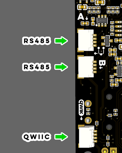
Each board will have a connector labeled “A” and “B”. These connectors are interchangeable; you can use either or both. Two are provided so that you can daisy chain between boards.
RS485 Cable
Section titled “RS485 Cable”With your control board, you will have received an RS485 cable, which you can use to connect boards together. It is keyed so that it will only insert into the connector in the right orientation.
If you need a replacement, you can use the same cables as Qwiic cables for short lengths. For longer runs (2+ feet), Bottango plans to have longer cables available for purchase in the future. You can also create your own cable. For long runs, you will want to ensure that the equivalent of the yellow and blue wires in the provided cable is a twisted pair in your own custom cabling. The connector type is JST SH 4-pin.
Caution While Connecting
Section titled “Caution While Connecting”Frequent plugging and unplugging of RS485 connectors into the board while powered up has a chance to cause voltage spikes and other related electrical transient events. Though there are protection components on the board, nothing is foolproof. To ensure the longest life of your control boards, it’s recommended that you wire up connectors while all boards are fully powered down.
Terminating Resistors
Section titled “Terminating Resistors”A chain of connected boards using RS485 needs to have a terminating resistor on both ends of the chain. Bottango control boards have that resistor built in, but you will need to enable or disable it correctly for each board to ensure proper communication. This is a requirement for proper communication over wired RS485, not an optional optimization.
This, as an example, is the switch on the back of Bottango Nova:
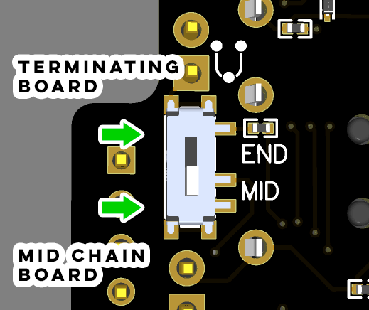
For boards that terminate either side of the daisy chain (or for both boards if you are using only two), set the END/MID switch on the back of the board to “END”. For boards that are in between the terminating boards, set the END/MID switch to “MID”. Be sure to have this correctly set before attempting to create connections in the software.
Enabling RS485 for Bottango Solar
Section titled “Enabling RS485 for Bottango Solar”Because there are a large number of features on Bottango Solar, the pins for servo headers 9 and 10 are also used for RS485 communication. If you use wired RS485 communication on Bottango Solar, you cannot also use servo headers 9 and 10. You also need to enable the RS485 transceiver using the switch on the back of the board.
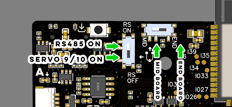
In the above, you can see on Bottango Solar both the enable / disable RS485 switch, as well as the terminating resistor switch.
You do not need to take any actions on Bottango Nova or Impulse to enable RS485 from a hardware perspective, only in software as outlined in the next section.
Switching from Wireless to Wired RS485 in Firmware
Section titled “Switching from Wireless to Wired RS485 in Firmware”As of the current software version, you will need to make a small change in the open-source firmware and then reupload it to switch the firmware to board-to-board communication using the RS485 transceiver rather than wireless communication. Familiarize yourself first with the process of compiling and uploading modified firmware.
In the step where you set the board type definition in BoardDefs.h, you will want to make one additional change. Locate the portion shown below that sets how to communicate board-to-board:
// relay#define RELAY_SUPPORTED#define RELAY_COMS_ESPNOW// #define RELAY_COMS_RS485You can see in the default above that board-to-board communication goes through ESP-NOW wireless. Disable ESP-Now wireless and enable wired RS485 by adjusting which lines are commented out as shown:
// relay#define RELAY_SUPPORTED// #define RELAY_COMS_ESPNOW#define RELAY_COMS_RS485Then reupload the modified firmware to your board, making sure to enable the correct board definition at the top of the file.
Once you have made this change and reuploaded the software, you will be able to follow the same steps in the guide to enable board-to-board communication:
Multi-Board Projects Setup GuideYou will create a bridge, and peers, etc. The arrangement of the bridge and peers in the daisy chain of connected boards does not matter; you do not need the bridge at any specific point. Note that the current application UI uses the labels “Create a Wireless Bridge” and “Connect to a Wireless Bridge” when you create a bridge or peer. When using RS485 you will use those same buttons, workflow, etc. When the software side finalizes for RS485 that will be more universal UI.
Reverse the change made above to switch back to wireless board-to-board communication.